Work / The sim rig

It didn’t stop
at a seat.

The sim I run isn’t really a racing game. It’s modeling tire temperature, grip, downforce and track conditions in real time, and it hands all of that back out as live telemetry. So the real project is hardware: getting that data onto your body, where you can react to it faster than you could ever read it. And since the cockpit has no extrusion to bolt to, I’ve had to design and print every single mount from scratch.

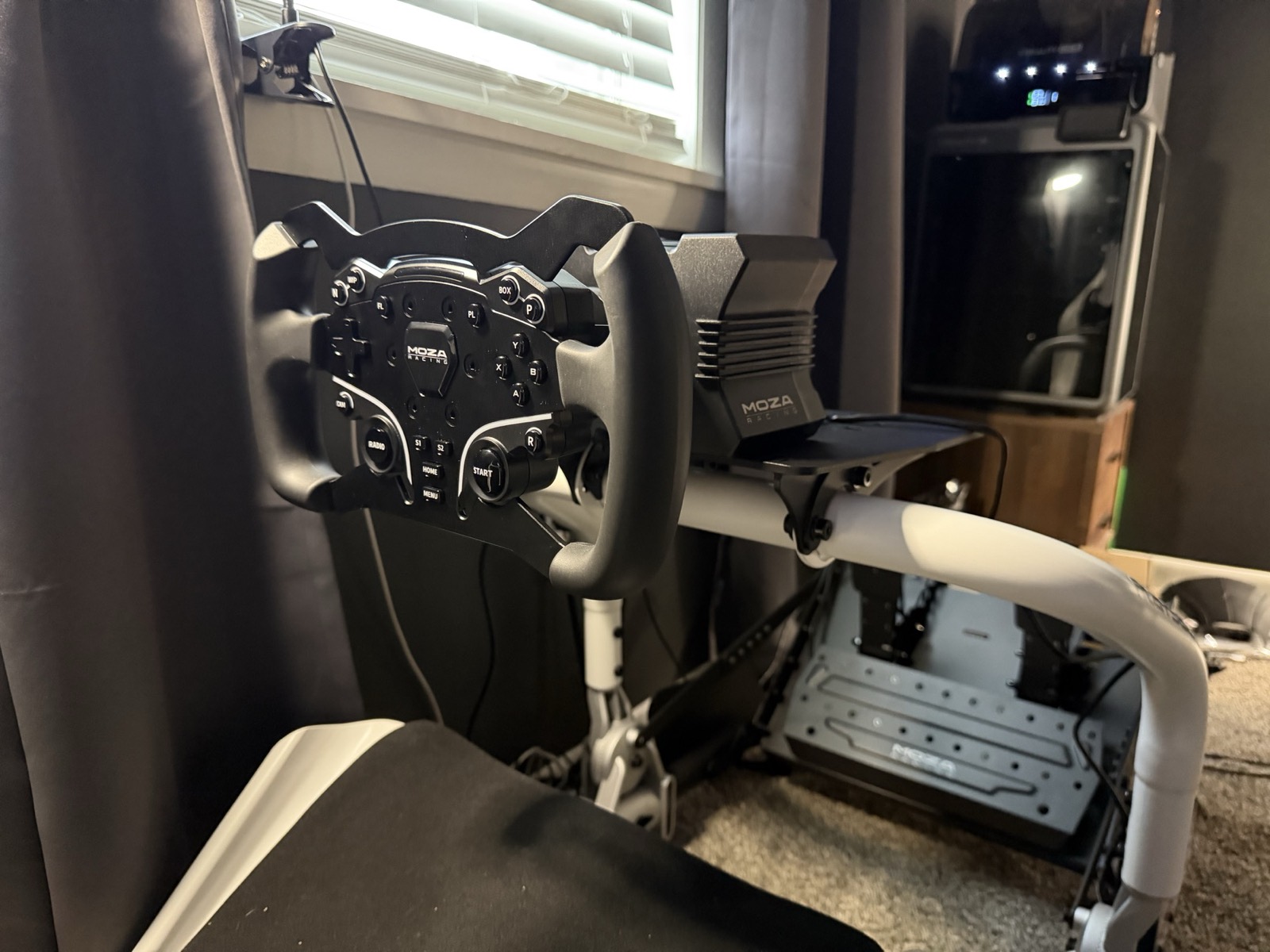
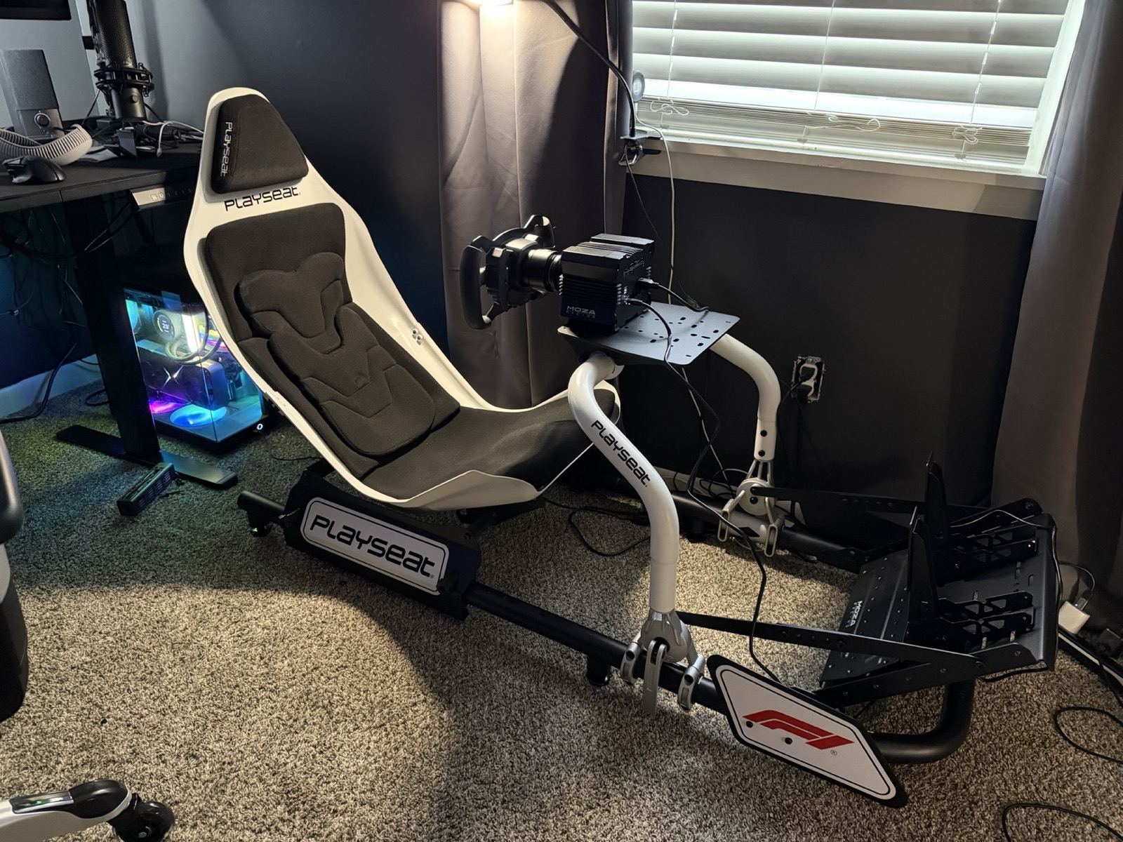
The Playseat Formula Instinct in its first week: white shell, a Moza R5 base and CS wheel on the wheel deck, pedals at the front, nothing else mounted.
The first week. An R5, a CS wheel, and nothing bolted to anything. Everything below happened to this seat.
5
Haptic channels,
spatially coded
2
Wind pods,
fully custom
0
Off-the-shelf
brackets used
ASA
Default structural
filament
The setup

What the sim
already knows.

In service

This is the part people miss. The sim is doing real physics. Every tire has a temperature and a grip level, the aero load changes with speed, and the track surface changes with the weather and with how many cars have driven over it. All of that is available as telemetry, live, every frame.

So the car already knows your left front is about to let go. The information is right there. It just has nowhere to go, because a screen can only show you so much and you’re busy looking at the corner.

So every system on this rig is a channel: something the car knows, sent to a spot on your body, fast enough that you react before you’d have read it. The hardware is a Playseat Formula Instinct cockpit and a Moza R12 V2 direct drive base with the KS formula wheel and SRP2 load-cell pedals, all running on a 9950X3D and RTX 5080.

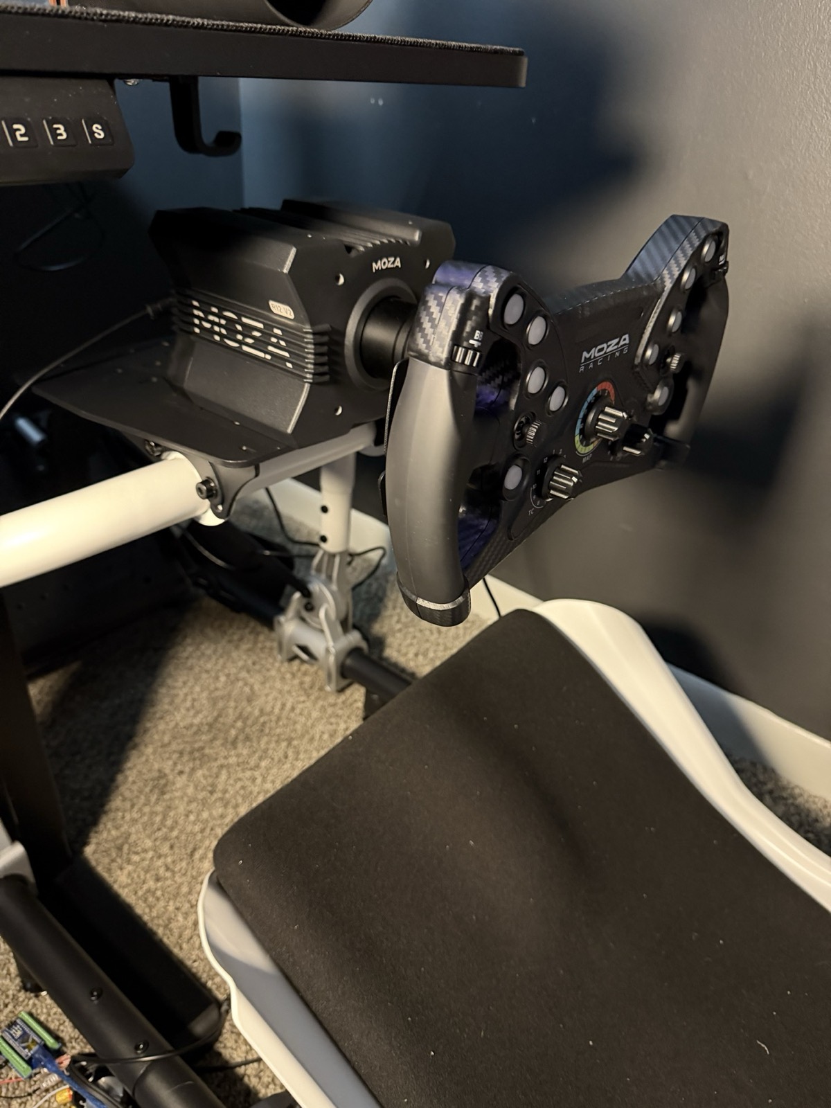
That’s the second set, by the way. I started on an R5 with the CS wheel and SRP Lite pedals and sent it all back almost immediately for something stronger. That pretty much sums up this whole project. It has never once stopped at the thing I actually bought.

The display is an Apple Vision Pro over CloudXR. No monitor at all. That raises the stakes on everything below, because there’s no dash light in the corner of your eye to fall back on. If you’re going to know something, you’re going to feel it.

And none of it bolts on. The Formula Instinct has no 8020 extrusion. No rails, no slots, nowhere to hang anything. On most rigs you’d just buy a bracket. Here every transducer, every fan pod and every motor mount has to be measured, modeled and printed before it can exist at all. That’s the constraint the whole build runs on, and it’s my favorite part: about ten minutes in, it stopped being an accessory build and turned into a fabrication project.

Core
CockpitPlayseat Formula InstinctNo extrusion, which shaped everything
WheelbaseMoza R12 V2 direct driveUpgraded from an R5
WheelMoza KS formulaUpgraded from the CS
PedalsMoza SRP2, load cell brakeUpgraded from SRP Lite
DisplayApple Vision Pro via CloudXRThe only display, no monitor
Host9950X3D · RTX 5080
FabricationCreality K2 Plus
The first set: a Moza R5 base with the CS wheel on the Playseat wheel deck, window light behind.
First set. R5 base, CS wheel.
The second set: a Moza R12 V2 base with the KS formula wheel, an Arduino and loose wiring on the floor below.
Second set. R12 V2, KS formula. The first went back almost immediately.
Inside the headset. The hand on the wheel is mine. Everything else is the sim.
Haptics

Five channels,
five places on the body.

Hardware here · mounting now

One big transducer under the seat is the easy version, and it works fine right up until two things happen at once, which in a race car is constantly. Everything blends into one big rumble and you’ve learned nothing.

So each cue gets its own spot on your body. A BST-1 under the seat pan does the whole-body low end: you feel the engine’s RPM through the middle of the rig, and every gearshift lands as an actual clunk through the seat.

Then four TT25-8 pucks. One under the brake pedal and one under the throttle, so when your left front starts to go and you’re a heartbeat from locking it up, you feel that in the foot that’s doing it. The other two sit at the back corners of the seat at shoulder-blade height, so if you clip a curb on the way through a turn, you feel it in the shoulder on that side.

That’s the whole point of the layout. Pelvis, shoulders and feet stay separate, so a lockup under braking doesn’t get buried under the road texture. You notice two things at once because they land in two different places. That’s how your body sorts out simultaneous sensations anyway.

A Douk Audio M4 drives the four pucks, a Nobsound Mini drives the BST-1, and everything runs through a Cubilux 7.1 USB card so SimHub can address each channel on its own. Next up is building out the ShakeIt library: per-car profiles, plus cues that replace the dash warnings a monitor rig would just show you.

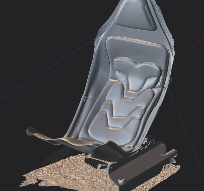
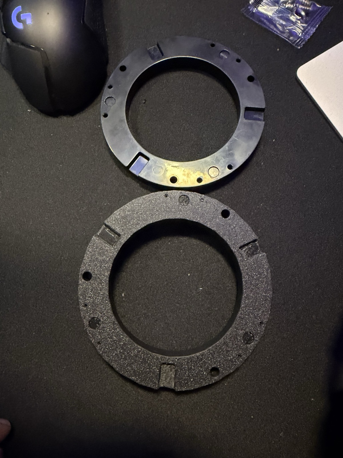
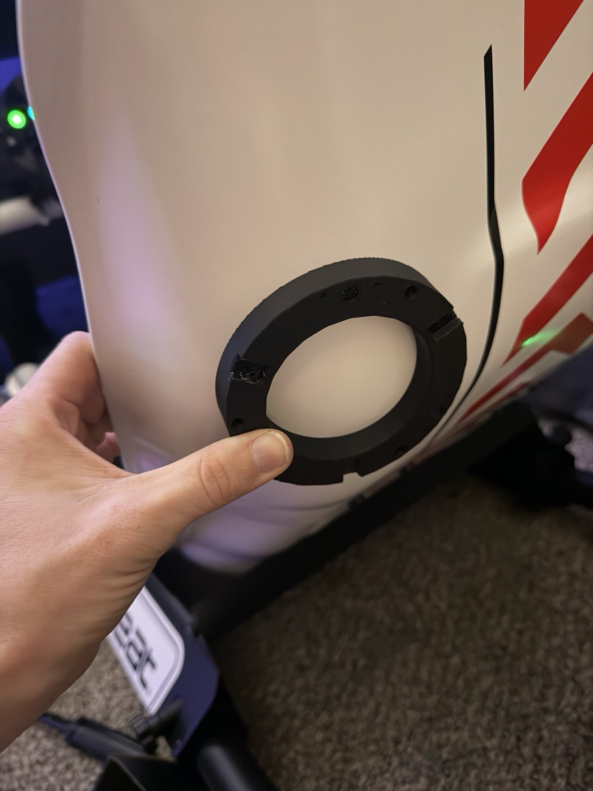
Then the mounts, which is where it stopped being plug-and-play. The pucks come with stock rings that expect something flat to bolt to, and the back of the Playseat is round. So I scanned the back of the seat with a Creality Ferret, pulled the scan into Plasticity, and modeled new rings that sit flush with the curve. They’re printed and about to go on.

The pedal pucks got the same treatment: I started from a downloaded mount, it didn’t fit my pedals, so I drew my own.

TT25-8 ×2 shoulders BST-1 pelvis · low end TT25-8 ×2 brake · ABS, lockup throttle · wheelspin SPATIAL CHANNEL CODING · SEAT TRACED FROM A PHOTO
Each cue gets its own spot, so effects that would blur together in one transducer land on different parts of your body. The seat is traced from a photo of the rig, and the pedals are drawn in.
A 3D scan of the Playseat seat shell open in Plasticity, with the scanned floor still attached underneath.
The seat, scanned with a Creality Ferret and pulled into Plasticity.
Two puck mounting rings on a desk: the stock injection-molded ring above, a black printed replacement below.
Stock mount on top, printed replacement below.
A hand holding the printed mounting ring against the rounded back of the white Playseat shell.
Checking the fit against the rounded back.
3D model · 1.4 MB Drag to turn
A rear puck ring, modeled against the scan.
3D model · 0.2 MB Drag to turn
The pedal puck mount, redrawn to fit the SRP2.
Wind

Wind, and where
the jet stops working.

Pods locked · brackets in redesign

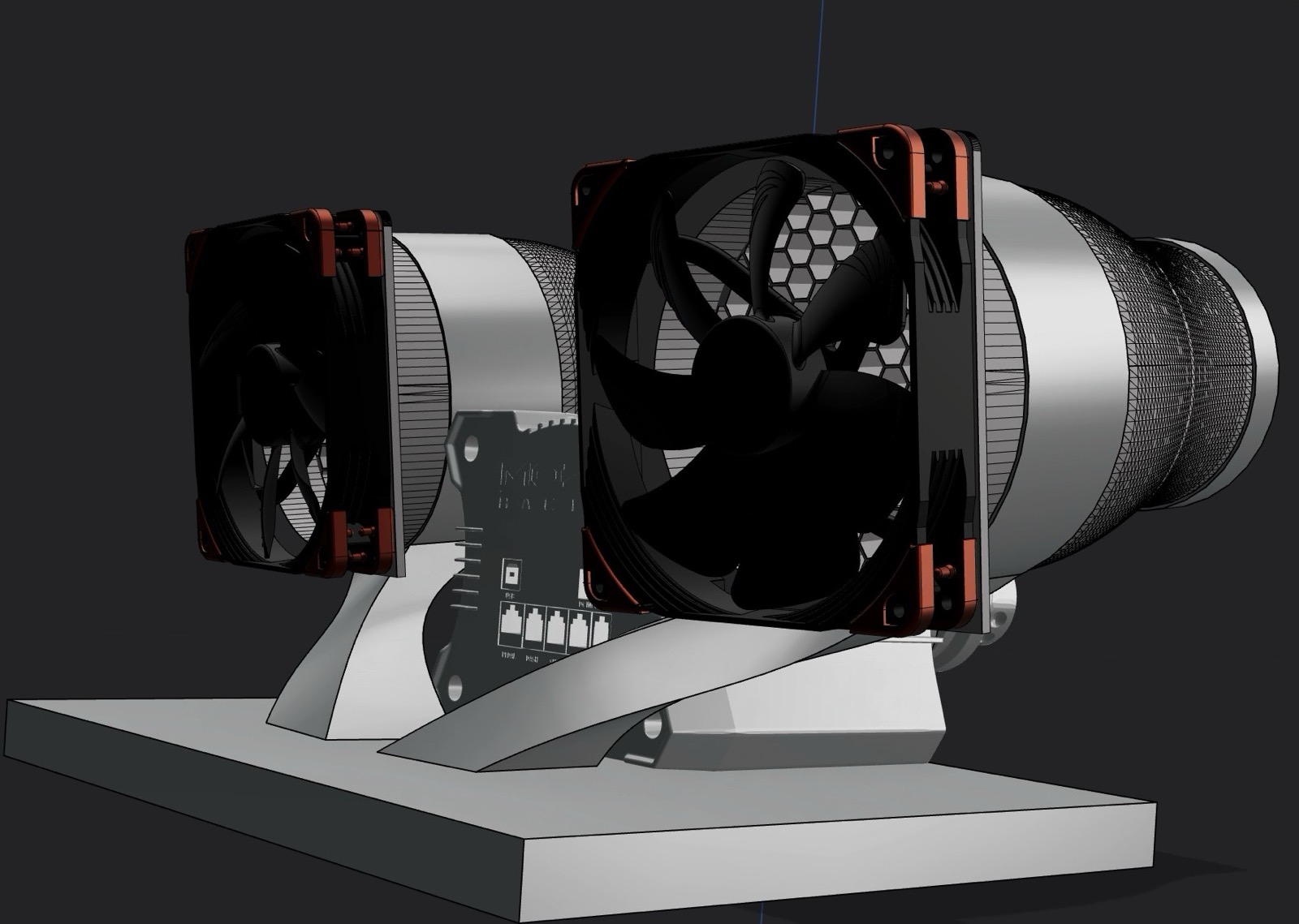
The idea is simple and stupid in the best way: at 200 mph it should be blowing a lot of air in your face, and when you brake for a turn it should drop off. Two Noctua NF-A14 iPPC-3000 fans, an Arduino Nano taking PWM straight off SimHub telemetry, and pods I designed myself: a honeycomb flow straightener into a Bell–Mehta contraction nozzle, 125 mm bore down to a 90 mm outlet over 190 mm.

To be clear about what it is: a speed and onset cue, not a recreation of real airflow at racing speed. Nothing sitting on a desk can do that. But what your face picks up is change, how fast the air builds and how fast it dies, and that’s most of the value anyway.

The number that decided the design: a free jet is down to about 60% of centerline velocity by ten outlet diameters. On a 90 mm outlet that’s roughly 900 mm. Past that, entrainment has eaten the gains and no amount of fussing with the nozzle gets them back.

So I stopped trying to perfect the contraction and put the effort into mounting close and aiming precisely, which is where it should have gone in the first place. Pod geometry is locked: exit centers, axis vectors, toe-in and pitch-up are all fixed. What’s still open is the brackets that tie the pods to the wheelbase, which I’m rebuilding in Plasticity now.

My first brackets lined up off the tips of the R12’s cooling fins, because that’s the surface you see when you look at the base. It’s the wrong one. The fins aren’t flat and they aren’t continuous, which is a real problem when a vibrating fan hangs off the bracket. The actual reference is a machined ring underneath, dead flat all the way around, at Y = 23.44, from 36.5 to 49.5 mm out. Finding it is why the mount turned into a collar that clamps around the whole base, and why I’m redrawing the brackets instead of tweaking them.

≈60% OF CENTERLINE BY 10 D, ~900 MM OUT HONEYCOMB BELL–MEHTA CONTRACTION SETTLE EXIT 55 20 100 15 190 mm Ø125 Ø90 POD SECTION · TO SCALE · JET SHORTENED
To scale, straight from the pod’s OpenSCAD file. The honeycomb sits at the inlet so its 0.8 mm webs print flat on the bed with no supports, and the contraction is a fifth-order curve with zero slope and zero curvature at both ends. The jet is still the real limit: ten outlet diameters is only about 900 mm.
Plasticity render of both wind pods on either side of the Moza R12 on a bracket, each Noctua fan seated behind its nozzle.
The collar bracket, both pods modeled around the R12 in Plasticity.
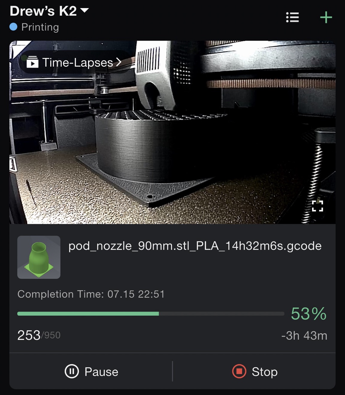
The Creality app showing the pod nozzle mid-print on the K2 Plus at 53 percent, with the honeycomb straightener visible, sliced for 14 hours 32 minutes in PLA.
The nozzle on the printer, in PLA, which on this build means it’s a test fit. A 14½-hour print just to prove the geometry.
3D model · 1.4 MB Drag to turn
The pod nozzle. The honeycomb is inside the flange end.
3D model · 1.4 MB Drag to turn
The collar bracket. A ring for each pod, joined to the collar around the base.
Belt tensioner

Two motors,
and a real limit.

Parts ordered · not yet built

You put a harness on when you sit down. You brake hard for a turn, and where you’d normally just pitch forward against nothing, the belt pulls tight across your chest, so it actually feels like the car is stopping. Get back on the throttle and it lets go.

Two NEMA 23 steppers on 15:1 planetary gearboxes, DM556T drivers, a 350 W 48 V supply, and an Arduino Nano reading linear hall sensors for position. Firmware is the free SimHub Belt Tensioner plugin. Every motor mount is custom CAD, obviously.

Left and right run independently, which gives you two axes. Both pulling together is longitudinal, the surge under braking and acceleration. One pulling harder than the other is lateral.

Here’s the catch, because it changes how you’d tune it: asymmetric belt tension is a directional cue, not a lateral G simulator. It tells you which way the car is loading up. It doesn’t make you feel pushed sideways in the seat, and nothing pulling on a shoulder strap ever will. Treat it as information and it works great. Chase realism with it and you’ve just built something that’s uncomfortable to sit in.

I still owe one measurement before anything gets printed: harness strap width, 50 or 76 mm, which decides the clamp variant.

Drivetrain
MotorsNEMA 23 × 2Independent left / right
Reduction15:1 planetary
DriversDM556T
Supply350 W · 48 V
FeedbackLinear hall sensorsPosition, via Arduino Nano
FirmwareSimHub Belt Tensioner plugin
Blocked onStrap width, 50 vs 76 mmSelects the clamp variant
What’s next

The showpiece,
eventually.

On the horizon

The end state is a body shell. Scan the finished rig, drop the scan into Fusion 360 as a reference body at around 100–150k triangles, then crop an actual F1 car body around it. Cut it off at the pedals, keep the left-side profile, and add the airscoop if it earns its place.

This is where it was always headed. Printed parts on this build get sanded, primed and finished, and nothing stays in raw layer lines. If every bracket on a thing was designed on purpose, it should look like it was on purpose, and a shell does that for the whole rig at once.

Sooner than that: a Moza RS V2 round wheel for GT and casual driving, and a Tesla Model 3 OEM wheel adapter, mostly because bolting a real car’s steering wheel onto a sim rig to play Forza is funny, and the adapter only takes an afternoon. Long term it’s an R21 Ultra on an aluminum profile rig, which would finally give me the extrusion this whole build has been working around.

Queued
Body shellScan → Fusion 360 crop~100–150k tri reference body
Round wheelMoza RS V2GT and casual
For funTesla Model 3 OEM wheel adapter
Long termR21 Ultra · aluminum profileThe extrusion this rig never had
What the build taught

Things worth
knowing first.

ASA for anything structural

Creep resistance and a glass transition near 100 °C, which matters when a bracket lives next to a stepper that gets warm. CF-PLA is fine as a bolt-through consumable. PLA is for test fits and nothing else.

Stiffness fails before strength

Printed brackets under constant haptic load don’t snap. They start to flex, and the effect you tuned quietly stops coming through. Design for stiffness and fatigue resistance, not the number on the filament spool.

Scan before you model

Any surface you didn’t make and can’t measure flat gets scanned first. The Playseat’s back is rounded, so the rear puck rings were modeled against a Ferret scan instead of a guess.

Test fit, then commit

Cheap material for the fit check, real material once the geometry is proven. Almost every part on this rig exists in at least two versions, and the first one was always wrong somewhere.

Find the real datum

The obvious surface usually isn’t the one to reference. Find the face that’s actually flat, continuous and machined, and build the bracket around that instead of whatever’s easiest to see.

Building something
similar?

I do the research part for other people too: a real parts list, in the order to buy and build it, with the mistakes already taken out.

Project planning Back to work